Light Folding: How LCD Light Guide Plate Lights Up Your Screen with Physical Magic
Abstract: Behind the slim and shiny LCD screen, there is a subtle optical engineering masterpiece hidden – LCD light guide plate. It is like an invisible magician of light, using the total reflection principle in PMMA material to transform the line light source at the edge into bright light that evenly covers the screen. This article deeply analyzes the core working principle, key material properties, microstructure design, light source coupling mechanism, uniformity control process and its wide application evolution of the light guide plate, revealing how this transparent thin plate achieves the visual feast of modern display technology.
1. Physical cornerstone: perfect control of total reflection effect
The core magic of the Lichtleitplatte comes from the total reflection effect of light at the interface of transparent media. When light is emitted from a high refractive index medium (such as PMMA, refractive index ≈1.49) to a low refractive index medium (such as air, refractive index ≈1.0), if the incident angle θ is greater than the critical angle, the light will be completely folded back into the interior of the medium with almost no energy loss. This principle is precisely described by Snell’s law (OSA Publishing). The PMMA light guide plate constructs an optical “trap” that allows the light entering it to be efficiently transmitted within the plate through continuous total reflection, laying the foundation for subsequent light extraction.
2. Material selection: PMMA’s optical excellence
It is no accident that PMMA (polymethyl methacrylate, commonly known as acrylic) has become the absolute mainstream material for light guide plates. Its ultra-high light transmittance (>92%) ensures minimal light transmission loss; its excellent physical stability and easy processing enable it to be made into large-area ultra-thin flat plates; its moderate refractive index (≈1.49) and the critical angle formed with air (≈42 degrees) are easy to use in engineering design. Compared with glass, it has significant advantages in light weight, impact resistance and cost. Manufacturers such as Mitsubishi Rayon continue to optimize their optical-grade PMMA formulas to reduce impurity scattering and pursue the ultimate light-guiding efficiency.
3. Light path deflection: “optical rebellion” caused by microstructures
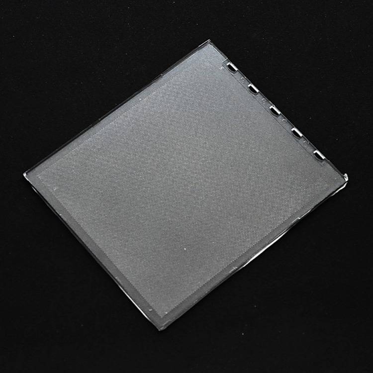
The real wisdom of the Lichtleitplatte lies in the microstructure design on its back (such as precision-printed white reflective dots, laser-engraved or molded microprism arrays). These structures are like preset “defection points”, destroying the perfect conditions for total reflection. When the dots distributed at a specific density and size encounter the light transmitted in the plate, the light is scattered and diffusely reflected, and some of the light is fortunately obtained with an exit angle less than the critical angle, and finally escapes from the working surface (perpendicular to the incident surface of the light source). This design cleverly achieves a 90° deflection of the light, “spreading” the entire plane with the line light source at the edge.
4. Source of energy: efficient coupling of light source and light guide plate
The original driver of this dance of light was the cold cathode fluorescent lamp (CCFL), which was fitted to the end face of the light guide plate as a line light source. With the evolution of technology, LED has completely replaced CCFL with its advantages of high brightness, long life, low power consumption and environmental protection. LED chips (point light sources) are precisely arranged on the side of the light guide plate (edge-lit), or placed below with special optical design (direct-down type, but requires thicker space). Efficient coupling requires precise matching of the light source emitting angle and the microstructure of the light guide plate light entry surface (such as sawtooth and lens array) to minimize the light entry loss – this is the key to the energy efficiency of the backlight module (SPIE: LED Backlight Unit Design).
5. The soul of vision: the ultimate pursuit of uniformity
The uniformity of screen display is the core of user experience. The dot/microstructure design of the light guide plate is the lifeblood of uniformity. Its distribution is by no means random, but is calculated through complex optical simulation: low density and small size near the light source to reduce near-end over-brightness; high density and large size far from the light source to compensate for the attenuation of light intensity at the far end. This forms a set of precise light compensation gradients. In addition, multi-layer optical films (such as diffusion film to further homogenize light, prism brightness enhancement film to converge light within the viewing angle, reflective film to recycle backscattered light) work together to create a bright, uniform, high-contrast final light output effect. Poorly designed dot distribution will cause “dark areas” or “bright bands” to appear on the screen.
6. Drive of evolution: application expansion and continuous innovation
Since the Japanese Mingtuo Company invented EDGE LIGHT technology in 1986 and established its mainstream position in laptop backlighting, light guide plate technology has continued to evolve. Applications have expanded from the initial notebook and digital camera screens to TVs, monitors, smartphones, tablets, car displays and even emerging VR/AR devices. Innovation focus: Ultra-thin (0.3mm or even thinner light guide plate), Ultra-large size (8K/ultra-large TV), Flexibility (curved screen application), High brightness & high uniformity (Mini-LED backlight combined with fine local dimming), Environmentally friendly material exploration**. These innovations push the boundaries of display device form and performance.
Zusammenfassung:
LCD light guide plate, this seemingly simple transparent thin plate, is actually the crystallization of optical wisdom and precision engineering. It is based on Snell’s law, uses PMMA material as a stage, and performs a wonderful light folding magic through the micro-structure design on the back – converting edge line light sources into uniform surface light. From the energy evolution of CCFL to LED, from empirical network layout to computer optimization design, from rigid to flexible form breakthroughs, light guide plate technology continues to drive the thinness, brightness and energy saving of display devices. It not only illuminates our digital vision, but also vividly interprets through its exquisite application of basic physical principles: The most profound scientific light will eventually turn into the light of wisdom that illuminates our daily lives.
FAQ
Q1: What is the core physical principle behind LCD light guide plates?
A: Total internal reflection (TIR) in PMMA acrylic, governed by Snell’s Law.
Q2: Why is PMMA the preferred material for light guides?
A: PMMA offers >92% light transmission, optimal refractive index (1.49), and superior manufacturability.
Q3: How do micro-dots on the guide plate create uniform light?
A: Strategically printed/scattered dots disrupt TIR, scattering light through the display surface.
Q4: Why did LEDs replace CCFLs in modern backlights?
A: LEDs provide higher efficiency, longer lifespan, and mercury-free design (SPIE research).
Q5: How do manufacturers prevent “hotspots” in edge-lit displays?
A: Gradual dot density modulation: sparse near LEDs, dense at distal ends.
Q6: What future innovations are shaping light guide technology?
A: Ultra-thin (<0.3mm) plates, mini-LED integration, and flexible substrates for curved displays.